In progress
SpaceX Super Heavy V3 Simulator
Rebuilding the physics, actuators and flight-control logic behind the world’s most powerful reusable booster.
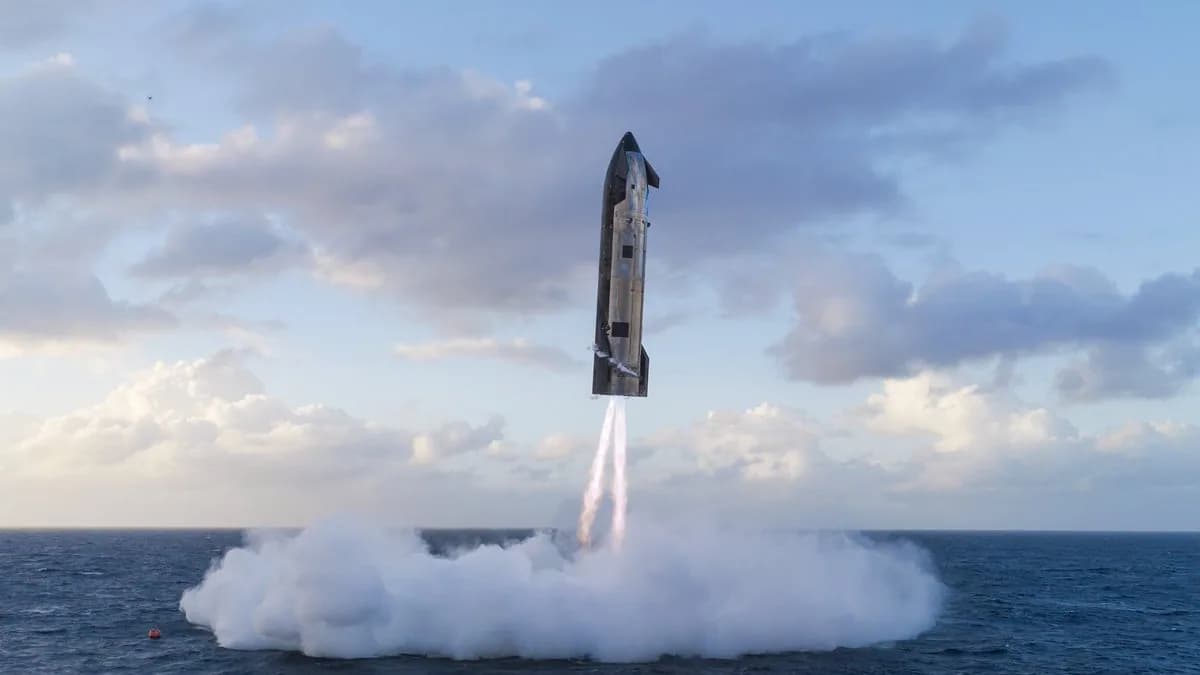
I have been fascinated by SpaceX and the engineering behind Starship for years, but the moment that truly stayed with me was the first successful Super Heavy tower catch during Starship’s fifth flight test in October 2024.
Watching a 70-metre booster fall back toward the launch site, restart its engines, cancel its velocity, align itself with the tower and end up suspended between two mechanical arms was almost difficult to process. I was completely glued to the screen. The result was spectacular, but what interested me even more was everything happening invisibly behind it: state estimation, trajectory planning, attitude control, engine allocation, fault handling and thousands of decisions executed in real time.
The idea for this project became concrete during the launch campaign for Starship Flight 12 in May 2026, the first flight of the V3 architecture. The initial attempt was stopped only seconds before liftoff because a hydraulic pin on the launch tower failed to retract. The problem was corrected and the vehicle launched the following day.
That sequence was a perfect reminder that aerospace systems are never just about making something fly. Every sensor, actuator, controller and safety condition has to work as part of the same system.
I decided that I wanted to rebuild a simplified version of that system myself. With modern coding tools such as Codex, attempting a project of this scale alone no longer meant spending a year writing every foundation from scratch. The tools accelerated implementation, exploration and iteration, while I remained responsible for the physical model, architecture, control logic and validation.
What started as an experiment around reinforcement learning gradually became a much broader project about simulation and flight control.
IMAGE 1 — Current simulator
Add a wide Unreal Engine screenshot of the complete Super Heavy booster during a controlled descent or landing burn.
The booster should remain the main focus, with the environment, engine exhaust and telemetry HUD visible around it.
The original question
The project started with a deliberately ambitious objective: train a controller capable of landing a reusable rocket booster.
My first idea was to create a reinforcement-learning environment in which an agent could observe the state of the vehicle and control its throttle, engine gimbal and aerodynamic surfaces. Algorithms such as SAC appeared well suited to the problem because the controls are continuous rather than discrete.
I also considered Model Predictive Control. Instead of learning a policy directly, an MPC controller predicts how the vehicle will evolve and selects the commands that minimize a cost over a future horizon:
Here, () represents the predicted vehicle state, () the desired trajectory and ( ) the actuator commands. The matrices () and () determine how strongly the controller prioritizes accuracy against control effort.
But both reinforcement learning and MPC depend on the same prerequisite: a simulation whose behaviour is coherent enough to trust.
Before trying to optimize the landing, I needed to understand exactly what was being optimized.
First stage: a physics engine I could understand
The first repository, Autonomous Rocket Landing Lab, is a custom 2D booster simulator written in Python.
I intentionally avoided beginning with a large aerospace framework. The objective was to implement the essential physics myself, keep the equations readable and make every force visible in the simulator.
The booster state is represented by:
where () and () describe position, () and () linear velocity, () the booster attitude, () its angular velocity and () the remaining fuel.
The controller acts on three values:
with throttle (), engine-gimbal angle () and aerodynamic steering command ().
The current mass and engine thrust evolve with fuel consumption:
The gimbaled thrust is projected into the world frame using the booster attitude:
These equations look simple, but they immediately reveal the coupling at the centre of the landing problem. A gimbal command can correct attitude, but it also changes the horizontal and vertical components of thrust. Stabilizing the booster and controlling its trajectory cannot be treated as completely independent tasks.
Adding atmosphere, rotation and landing constraints
The simulator includes gravity, fuel consumption, variable mass, atmospheric density, passive aerodynamic forces, aerodynamic steering, rigid-body rotation and ground contact.
Atmospheric density decreases exponentially with altitude:
The aerodynamic forces then depend on dynamic pressure:
This means that grid-fin-like controls become more effective as airspeed and atmospheric density increase, while becoming almost useless in thin atmosphere or at very low speed. A controller therefore cannot rely on the same actuator authority throughout the descent.
Engine gimbal also generates a torque around the booster’s centre of mass:
with () representing the distance between the centre of mass and the engine force application point. Angular acceleration follows from:
where the booster’s moment of inertia is approximated as a slender rigid body:
The equations are integrated using a semi-implicit Euler method. It remains simple enough to inspect while providing better numerical behaviour than a direct explicit update:
A successful landing is not defined by simply touching the ground. The final state must respect simultaneous limits on vertical speed, lateral speed, target error, attitude and angular velocity:
Failing any one of these conditions turns the touchdown into a crash.
IMAGE 2 — The original 2D laboratory
Add a screenshot of the PyGame simulator running an offset-recovery scenario.
Enable the physics-debug overlay so the image shows the trajectory, landing target, thrust vector, aerodynamic forces and live vehicle state.
Why I stepped back from reinforcement learning
The first prototype was initially meant to become a Gymnasium environment for training a SAC agent. However, working on the physics changed my understanding of the problem.
A reinforcement-learning agent does not know whether the environment is realistic. If the physics contain a sign error, an unstable integration step or an unrealistic actuator, the agent may learn to exploit that mistake. A successful reward curve can therefore hide a completely invalid controller.
The same issue exists with MPC. Its predictions can only be as useful as the model used to generate them.
I changed the order of the project and focused first on foundations:
- separating physics, simulation, controllers and rendering
- defining configurable scenarios through YAML
- visualizing forces and control commands
- validating equations with unit tests
- adding precise manual controls
- implementing a deterministic landing baseline
- documenting the assumptions and known limitations
A basic PID controller provided the first reference:
It is less sophisticated than MPC or reinforcement learning, but it is understandable and debuggable. If the vehicle oscillates, overshoots or becomes unstable, I can inspect the error, gains, actuator saturation and physical response directly.
This baseline became essential for evaluating more advanced methods later. A learned controller is only interesting if it can demonstrate a measurable advantage over a simpler one.
From a 2D laboratory to a Super Heavy V3
The second repository, SpaceX Super Heavy V3 Simulator, represents a major change in scale.
The project moved from a generic 2D booster to a complete 3D vehicle built with Unreal Engine. This introduced six-degree-of-freedom motion, quaternion-based attitude handling, real-time rigid-body physics, individual actuators, cameras, telemetry and mission sequencing.
The simulated Super Heavy V3 is composed of 33 individually identified Raptor engines:
- 20 fixed outer engines
- 10 gimbaled inner engines
- 3 gimbaled centre engines
Each engine exposes a throttle target and an actual throttle. Gimbaled engines additionally expose pitch and roll targets. Commands are subject to range and rate limits instead of being applied instantaneously.
The three grid fins follow the same approach, with individual angles, deflection limits and movement rates.
This was an important architectural decision. The booster is not controlled as one abstract thrust vector. Commands eventually have to be allocated to physical actuators, each with its own capabilities and limitations.
IMAGE 3 — Engines and grid fins
Create a two-part visual:
- a bottom view showing the complete 33-engine layout;
- a close-up of a gimbaled engine and one grid fin in Unreal.
If possible, display actuator identifiers or command values to make the individual control structure visible.
Guidance, Navigation and Control
The current simulator is structured around a Guidance → Navigation → Control architecture.
Navigation reads the physical state from Unreal, converts centimetres into SI units and computes the vehicle position, velocity, attitude and angular rate relative to the mission target.
Guidance determines where the booster should go. Depending on the current phase, it produces targets such as a vertical velocity, altitude, position or desired attitude.
Control turns the difference between the target and measured state into thrust, gimbal and grid-fin commands.
The complete runtime flow is:
Mission profile
    → Navigation state
    → Flight-phase sequencer
    → Guidance targets
    → Control laws
    → Actuator command
    → Engine and grid-fin allocation
    → Vehicle physics
    → Telemetry
C++ owns the mission state, navigation, guidance, controllers, validation and telemetry. Blueprints own meshes, pivots, child actors, cameras, exhaust effects and the final application of individual actuator commands.
This boundary lets the control system remain independent of Unreal-specific asset details. A future MPC or reinforcement-learning controller will produce the same actuator-command structure as the current PID implementation.
IMAGE 4 — GNC architecture
Add a clean architecture diagram showing the flow from mission profile to vehicle physics.
Use separate visual groups for:
- Guidance
- Navigation
- Control
- Actuator allocation
- Unreal vehicle
- Telemetry
Controlling a mission, not a single manoeuvre
A booster cannot use one set of targets and controller parameters during its entire flight.
The simulator therefore represents a mission as a sequence of phases:
- ground idle
- liftoff
- ascent
- main engine cutoff
- coast
- boostback
- entry
- approach
- landing burn
- touchdown
- abort
Each phase can define its own guidance mode, control frequency, target velocity, target attitude, PID gains, engine groups, actuator limits and transition conditions.
During ascent, the objective may be to follow an altitude and attitude profile. During boostback, the booster must reverse its horizontal velocity. During entry, aerodynamic control becomes increasingly important. During the final landing burn, the system must simultaneously cancel vertical velocity, remove lateral error and keep the booster upright.
This phase-based architecture makes each problem easier to reason about while still allowing a complete mission to run as one continuous sequence.
Observability as part of the control system
A simulation becomes difficult to improve when it only shows whether the vehicle landed or crashed.
The Unreal version therefore exposes live telemetry and internal autopilot state through a dedicated HUD. It displays the current mission phase, position, velocity, attitude, controller errors, thrust request and actuator state.
This is not only a visual feature. It is the main debugging interface for understanding why the controller made a decision and whether the resulting vehicle response matched the model.
The same observability will eventually make it possible to compare several controllers using concrete metrics such as:
- landing accuracy
- fuel consumption
- maximum attitude error
- control effort
- recovery time
- resistance to disturbances
- success rate across randomized initial states
IMAGE 5 — Autopilot telemetry
Add an in-flight screenshot with the telemetry HUD visible during the landing or approach phase.
The most useful values would be altitude, vertical velocity, target error, attitude error, throttle command, active engines and current flight phase.
Where the project stands today
The current simulator includes a usable 3D vehicle, all 33 engines, three grid fins, propulsion forces, actuator interpolation, cameras, exhaust effects, navigation, mission profiles, flight phases, PID foundations and live telemetry.
Several parts are still intentionally incomplete. Grid-fin aerodynamics are not yet fully connected to the vehicle dynamics, lateral landing guidance is still evolving and the physical parameters remain approximations based on public information rather than a high-fidelity SpaceX model.
The next stages are focused on:
- implementing a more complete aerodynamic force and torque model
- completing lateral guidance toward the landing target
- tuning and validating the landing-burn controller
- introducing wind, sensor noise and actuator uncertainty
- building repeatable mission-validation scenarios
- adding LQR and MPC behind the existing control interface
- reconnecting the simulator to reinforcement learning once deterministic baselines are reliable
IMAGE 6 — Project evolution
Add a side-by-side comparison between the first Python simulator and the current Unreal Engine version.
Suggested caption: From understanding the equations to controlling the complete vehicle.
More than a rocket animation
The most important lesson from this project is that autonomous landing is not one algorithm.
It is a chain of models and systems that must remain consistent: physics, numerical integration, navigation, guidance, control, actuator allocation, mission sequencing and telemetry.
The project began because I wanted to train an agent capable of landing a rocket. Building it made me realize that the more interesting challenge was understanding everything the agent would depend on.
Modern coding tools made it realistic for me to explore a project of this scale alone, but they did not remove the engineering work. Every abstraction still needs to represent something physical, every controller needs measurable behaviour and every successful landing needs to be explainable.
That is what I ultimately want this simulator to become: not only a convincing reproduction of a Super Heavy landing, but a complete experimental platform where different control strategies can be implemented, observed and compared on top of the same vehicle.
Built with
- C++
- Unreal Engine 5
- Blueprints
- Python
- Pygame
- NumPy
- PID control
- MPC models